
Edition 01/2003
Suivre ces instructions en parallčle avec le TCI planche QPL48.00
Follow these instructions with the parts catalog opened.
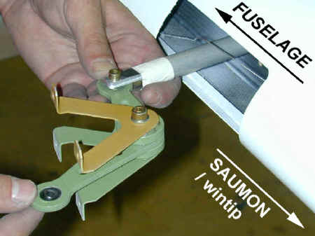
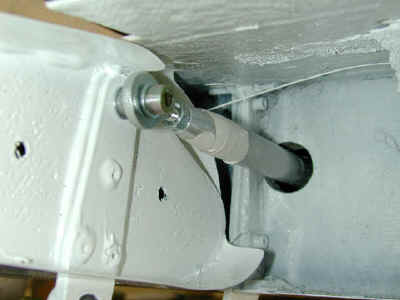
- Montez les renvois inverseurs sur leurs supports, derričre le couple 4.
Mettez des rondelles larges sous les écrous.
N'oubliez pas l'entretoise entre le renvoi et le support supérieur.
- Install the reversing levers on their supports, behind frame 4. Put large washers
under the nuts.
Don't forget the spacer between the lever and its upper support.
- Montez la biellette de commande entre le pied de manche et le renvoi
inverseur. Note : mettez une rondelle D.6x12 entre le pied de manche et la rotule de la
bielle pour permettre un plus grand débattement angulaire.
- Fit the control rod between the stick root and the reversing lever. Note : put a
D.6x12 washer between the stock root and the eye ball, to allow more angular play.
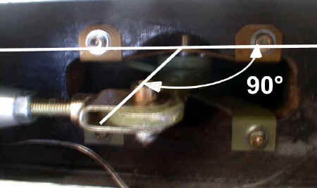
- Réglez la longueur des deux bielles pour que , quand les manches sont
au neutre, les deux renvois soient perpendiculaires au couple 4 (= parallčles ŕ l'axe
avion).
- Set the rod length so that, when the sticks are in neutral position, both levers are
perpendicular to the frame (= parallel to aircraft axis).
- ATTENTION ŕ l'orientation de l'embout ŕ rotule : actionnez le
manche ŕ fond dans toutes les directions pour vérifier que la bielle ne soit jamais en
butée en torsion. Bloquez l'embout avec le contre-écrou.
- ATTENTION check the eye ball rod end orientation : move the stick in all (and
combined) directions to make sure no rod reaches any end stop in torsion. Tightrn the
set-nuts.
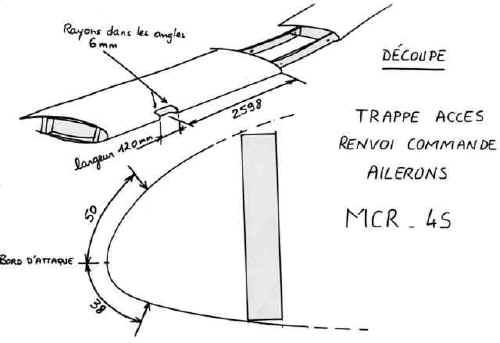
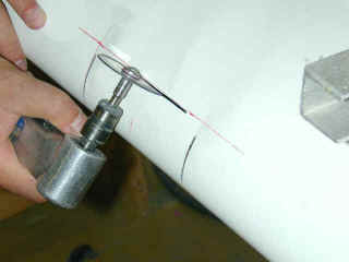
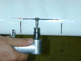
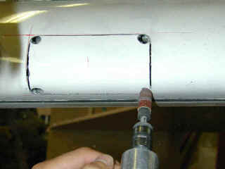
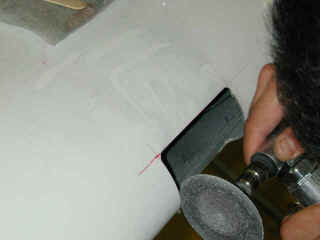
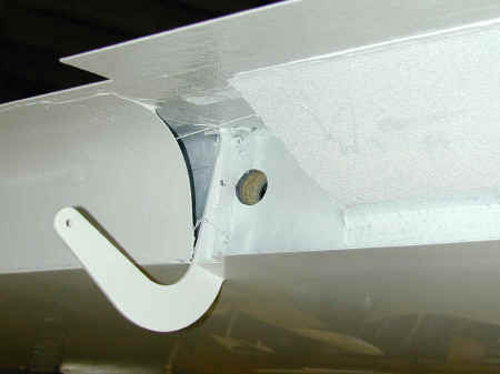
- Découpez les trappes d'accčs aux renvois d'ailerons dans le bord
d'attaque des ailes. (suivre les marques du moule)
- Cut the aileron bellcrank acces doors in the wings leading edges. (follow the
engraved lines)
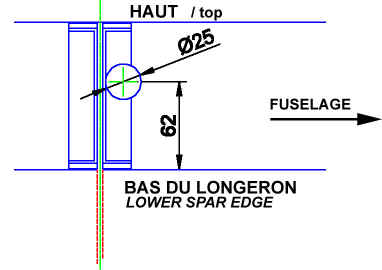
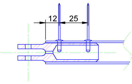
- Percez ŕ l'aide d'une scie cloche, le passage de la biellette de
commande de l'aileron dans le longeron arričre :
- diametre 25 mm
- axe du trou ŕ 62 mm depuis le bas du
longeron
- le bord du trou tangeant au rebord de la
boite de potence carbone.
Allez y doucement pour ne pas abimer le longeron.
- Drill with a hole saw, the aileron control rod passage hole in the rear spar :
- diametre : 25 mm
- hole axis 62 mm from the bottom edge of the
spar
- the hole is tangent to the
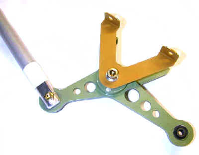
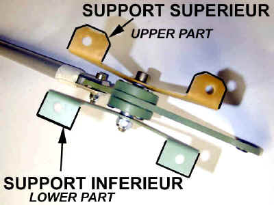
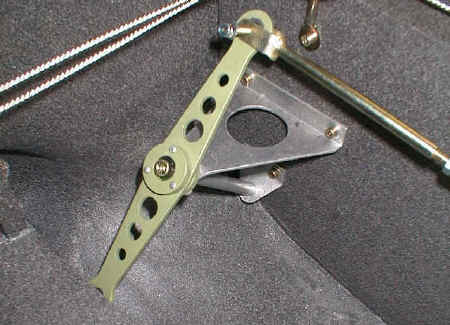
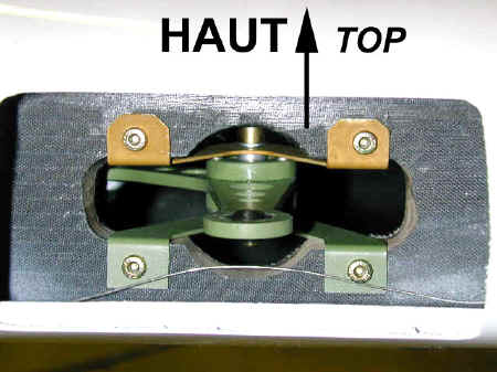
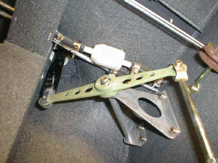
- Assemblez les renvois de commande sur leurs supports. Attention, il y a
un support supérieur et un support inférieur. Voir photo.
Faites un assemblage droit et un assemblage gauche.
N'oubliez pas les entretoises de 5 mm.
Montez la bielle de commande d'aileron sur le petit bras du renvoi.
- Assemble the aileron control bellcranks on their supports. Take care : there is a
upper and a lower support. See picture above.
Make one left and one right assembly.
Do not forget the 5 mm long spacers.
Fit the control rod on the small arm of the bellcrank.
- Enfilez l'ensemble (avec la bielle) dans le longeron avant. Faites
sortir la bielle dans le trou du longeron arričre.
Attention ŕ l'orientation : les supports biseautés au dessus, le petit bras du guignol
vers le fuselage.
Fixez les supports au longeron (les écrous prisonniers sont déjŕ présents dans
l'aile).
- Fit the whole assembly (with the rod) into the front spar hole. Slide the rod in the
hole in the rear spar.
Mind the orientation : the upper supports with bevelled edges on top, the small arm of the
bellcrank in the fuselage direction.
Fix the supports on the spar (captive nuts are already installed in the wing).
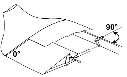
- Réglez la longueur de la bielle pour que, quand l'aileron est au neutre
( = aligné avec le winglet), le grand bras du guignol soit perpendiculaire au longeron.
Au moins 9 mm de filetages doivent ętre engagés dans l'embout (ŕ vérifier ŕ l'aide du
petit trou)
- Set the rod length so that, when the aileron is in neutral position ( = aligned with
the winglet), the long arm of the bellcrank is perpendicular to the spar. At least 9 mm
threads must be engaged in the rod end (check thanks to the small hole in the rod end).
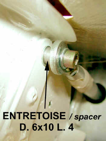
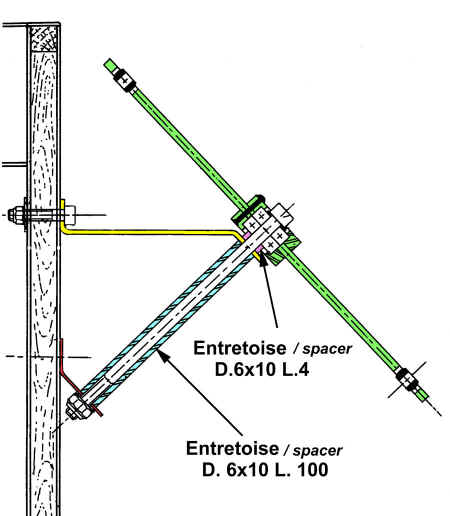
- Fixez la bielle ŕ l'aileron, avec une vis CHC ou H de
6x40 (pour qu'il y ait une partie lisse dans les sections en cisaillement). N'oubliez
pas l'entretoise de 6x10 L4.
- Fix the rod on the aileron, with a CHC or H head 6x40 screw (so that there is
a non-threaded part in shear stressed sections). Do not forget the 6x10 L 4 spacer.
A faire aprčs montage de l'aile sur le fuselage
To be done after the wing is attached on the fuselage.
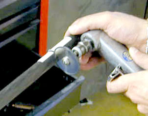
- Découpez les deux grands tubes carbone de bielles de commande ŕ 2655
mm.
Note : utilisez un outil ŕ disque diamant, et
serrez le tube carbone tout doucement dans l'étau, en le protégeant avec un
chiffon, pour éviter de le faire éclater.
- Cut both main carbon rods to the length of 2655 mm.
Note : use a diamon-coated disc, and tighten
the carbon tube very gently in the bench vice, proteceted with a cloth, to avoid
splitting it.
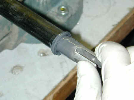
- Poncez l'intérieur des tubes et les embouts, et dégraissez bien.
- Abrade inside the tube, and the rod ends. Degrease carefully.
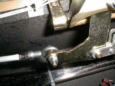
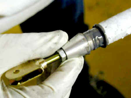
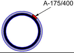
- Collez les embouts "chapes" ŕ la colle époxy A-175/400 :
- enfilez en tournant pour bien répartir la
colle
- l'embout doit ętre enfilé dans le tube
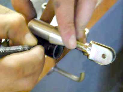
jusqu'au niveau de la chape (Utilisez 2 vis cirées pour faire butée (voir photo)
- maintenez -les immobiles pendant le séchage
avec du scotch.
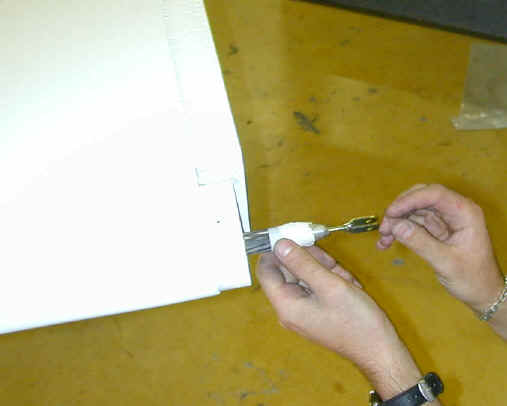
- Glue both rod ends with A-175/400 epoxy glue :
- turn the rod end when you slide it in the
tube, to spread the glue correctly
- The rod end must be fitted into the tube with
the end of the clevis notch flush witht the tube edge. Use two waxed screws as shown
on the picture to hod the distance
- and hold them with tape durind drying.
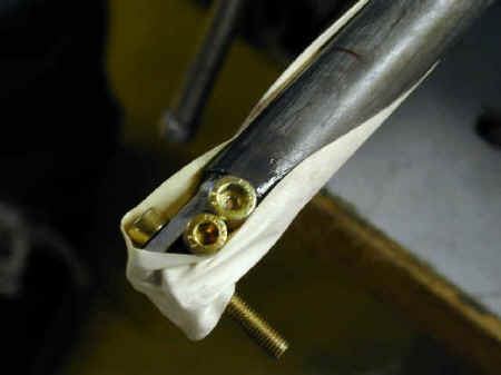
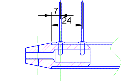
- Aprčs séchage (mini 24 h), percez et rivetez les enbouts aux cotes
indiquées ci-dessus (2x2 rivets en vis ŕ vis)
- After at least 24 hrs, rivet the rod end on the tube with 4 rivets 3.2x8 round head
rivet epoxy coated. See rivet location above. (2x2 rivets facing each other)
- Montez la chape réglable sur l'embout de bielle cônique (sans serrer)
- Fit the setting clevis on the conic rod end (don't tighten it)
- Scotchez l'embout de bielle cônique sur la bielle
- Tape the rod end on the tube.
- et enfilez la bielle dans l'aile.
- and slide the rod in the wing.
- Branchez la bielle au renvoi inverseur.
- connect the rod to the fuselage levers.
- Réglez les manches au neutre
- Set the sticks in neutral position
- verifiez que les renvois inverseurs sont bien parallčles ŕ
l'axe avion (au besoin, réglez les biellettes).
- check both levers are parallel to the fuselage axis (reset the
small rods if required).

- Vérifiez que l'embout cônique est enfoncé ŕ fond dans le tube
carbone.
- Check the conic rod end is thoroughly inserted in the carbon tube.
- Réglez la chape pour mettre l'aileron au neutre (vérifiez que
le renvoi est perpendiculaire au longeron)
- Set the clevis to set the aileron neutral (check the bellcrank front arm is
perpendicular to the spar)
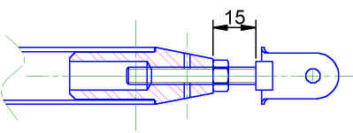
- ( Au besoin, pour avoir une possibilité de réglage ultérieur plus
importante, vous pouvez encore raccourcir la bielle pour avoir 15 mm de réglage
disponible. )
- ( If required, to allow a larger range of future resettings, you can shorten the rod
again by a few mm, to leave 15 mm between the rod end tip and the clevis base. )
- Collez et rivetez l'embout de bielle, comme précédemment. Voir
position des rivets ci-dessus
- glue and rivet the rod end, as previously. See rivet location above.
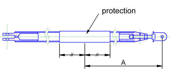
POSITION DE LA PROTECTION DE BIELLE AU NIVEAU DU GUIDE A ROULEMENTS
ROD PROTECTION IN THE BALL-BEARING-GUIDE AREA
Il y a un guide-bielle intermédiaire dans le bord d'attaque de l'aile,
pour empęcher la bielle de flamber en compression.
There is a 3-ball-bearings guide in the wing leading edge, to prevent the rod bending
under compression.
Il faut positionner une protection en alu sur la bielle pour que les
roulements n'usent pas le tube carbone.
It is necessary to put an aluminium protection on the rod to prevent the ball-bearings to
wear the carbon tube.
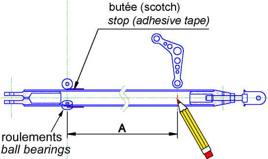
Enrouler du scotch sur la bielle pour faire une butée. (Diamčtre
+/-23mm)
Wrap some tape around the rod to make a stop (diametre +/-23mm)
Enfiler la bielle dans l'aile par le côté saumon, jusqu'ŕ ce que le
scotch bute contre les roulements du guide.
Slide the rod in the wing from the wingtip, until the tape stop touches the guide ball
bearings
Faire une marque sur la bielle en face du levier de commande (attention
celui-ci doit ętre au neutre !)
Mark the rod exactly in front of the bellcrank axis (be careful, the bellcrank must be
neutral !)
Mesurer la distance A entre la butée et la marque.
Tracer sur la bielle la position de la protection , en reportant A depuis l'axe de la chape réglable
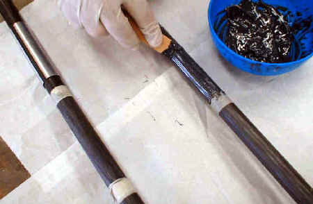
- Délimitez l'emplacement de la protection avec du scotch
- Delimit the protection glueing surfage with adhesive tape.
- Poncez trčs légčrement le tube en carbone.
- Abrade very gently the carbon tube.
- Collez ŕ l'époxy A175/400 la protection sur la bielle, et mettez le
collage en pression avec des colliers de serrage en plastique. (pas de colliers
métalliques ŕ vis !)
- Glue with A-175/400 epoxy the protection on the rods, and put the gluing under
pressure with plastic cable ties ("ty-raps"). (No metallic hose clamp !)
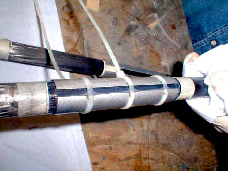
- Aprčs séchage, remplir la fente avec de la colle
- After drying, fill the notch with glue.
- Quand tout est sec, poncez les bavures pour avoir une surface lisse et
ronde.
- When everything is dry, sandpaper the burrs to get an even round surface.