
Édition 10/2003
TRAIN PRINCIPAL OLÉOPNEUMATIQUE MCR 4S
MCR-4S OIL-PNEUMATIC MAIN UNDERCARRIAGE LEG
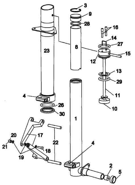
Vue éclatée / Exploded view
Recommandation / Advice
Suivez ce manuel de montage ŕ l'aide du TCI planche QPL6400.
Follow these mounting instructions with the Parts Catalog page QPL6400.
Mise en garde
- ATTENTION la partie chromée de la jambe mobile ( rep. 1 ) est un élément
ne devant pas ętre rayé, frappé, serré ou subir toute autre action mécanique risquant
de détériorer la géométrie ou l'état de surface, ce qui risquerait d'avoir pour
conséquence un mauvais fonctionnement du train ( fuites , blocages...)
- ATTENTION the chromium-plated part of the moving leg (No. 1) must not be scratched,
dented, hurt, tightened or suffer from any mechanical stress that may damage the shape or
the surface condition, because this would cause a bad functioning of the undercarriage
(leaks, jamming...)
- Les joints fournis pour le train ne doivent pas ętre montés ou manipulés
avec des objets risquant de les endommager (tournevis, réglet ......).
Ces joints ne sont compatibles qu'avec le type de fluide hydraulique en référence (norme
AIR 3520). N'utilisez JAMAIS un autre type de liquide hydraulique (DOT4 en particulier).
- The joints provided must not be installed or handled with tools that could damage
them (screw diver, metallic ruler...).
These joints are compatible only with the hydraulic fluid provided (norm AIR 3520). NEVER
use any other type of hydraulic fluid (especially DOT4).
- S'assurer d'effectuer les opérations de montage dans un lieu sans
poussičre.
- Work in dust-free conditions.
Montage du train
Leg assembly
NOTE: Toutes les pičces sont identiques pour les trains droite et gauche sauf
la partie mobile ( rep. 1 ).
L'élément dessiné sur la planche de TCI est le DROIT, la partie gauche est son
symétrique.
Note : all the parts are identical on the left and on the right assy, except the
moving leg (No. 1).
The assembly represented on the drawing is the RIGHT one, the left one is symmetrical.
Opérations ŕ effectuer en préliminaire
Preliminary step
- Avec un démonte obus, retirer les obus des valves ( rep. 16 ). Dégraisser
soigneusement les valves ( rep. 16 ) et les 2 trous taraudés (du rep. 12). Coller les
valves avec de la colle époxy A-175/400. Visser ŕ la main jusqu'ŕ fond de filet
.Attention l'étanchéité de ce collage est essentielle. ATTENTION, ne laissez aucune
trace de colle DANS la valve.
- With a valve key, remove the cores from the valves (No. 16). Carefully degrase the
valves and the holes in the (No. 12). Glue the valves in the (N0. 12) with A-175/400 epoxy
glue, screw them in by hand, to thread root. Be careful since it is essential that glueing
is perfectly airtight. ATTENTION, do not leave any trace of glue inside the valve.
Opérations ŕ effectuer aprčs séchage complet ( 24h ŕ 20°C )
To be done after the glue has completely cured (24 h at 20°c)
- Identifier les différents joints en les posant sur la feuille fournie dans le kit.
- Identify the different type of joints thanks to the descriptive sheet of paper
provided with the kit.
Note: les "collages" sont ŕ effectuer avec de la "Bloc presse Loctite
638"
Note : the following "glueings" must be made with Loctite 638 glue.
Équipement intérieur
Inner equipment
- Coller le piston (rep. 10) sur la tige ( rep. 11 ). Les trous obliques
dans le piston sont ŕ orienter du bas vers le haut (les trous s'orientent vers la tige )
- Glue and screw the piston (No. 10) on the rod (No. 11). The oblique holes in the
piston must be orientated to the collar on the rod.
- Enfiler le joint butée ( rep. 29) sur la tige (rep. 11)
- Slide the mechanical stop joint (No. 29) on the rod (No.11)
- Enfiler la rondelle ovalisée ( rep. 13 ) sur la tige (rep. 11)
- Slide the oval washer (No.13) on the rod (No.11)
- Coller le bouchon ( rep. 12 ) sur la tige (rep. 11 )
- Glue the plug (No.12) on the rod (No.11)
- Mettre en place le joint ( rep. 27) sur le bouchon ( rep. 12 ) avec de
la graisse Bendix ( rep. 33).
- Install the o-ring (No.27) ont the plug (No.12) with Bendix grease.
Jambe mobile
Moving leg
- Coller l'embout de fusée (rep. 2) dans la fusée, il doit affleurer sans dépasser.
- Glue the tip (No.02) in the wheel axle, it must be flush.
- Passer ŕ l'intérieur de la jambe mobile ( rep. 1 ) un produit de protection style
WD 40.
- Spray an anti-corrosive product (type WD-40) inside the moving leg (No.1).
- Enfiler la butée ( rep. 8 ) dans la jambe. Les encoches doivent ętre positionnées
vers le bas , la plus grande encoche est du coté opposé ŕ la fusée.
- Slide the limit stop (No.8) inside the moving leg. The notches must be fitted on the
wheel axle, the larger notch goes on the side opposed to the wheel.
- Mettre en place le joint ( rep. 28) sur le bouchon ( rep. 9 ) avec de la graisse
Bendix ( rep. 33).
- Install the o-ring (No.28) on the plug (No.9) with bendix grease (No.33).
- Enfiler le bouchon avec son joint dans la jambe (rep. 1) , une fois la gorge de
réception du circlips passée , pousser le bouchon jusqu'ŕ l'amener en contact avec la
butée. Pour pousser le bouchon ne pas utiliser d'outil risquant d'endommager l'intérieur
de la jambe, utiliser par exemple un morceau de bois ( sapin ).
- Slide the plug with its o-ring inside the leg (No.1), once the circlips groove is
passed, push the plug further in, until you reach the limit stop. To push the plug, do not
use a tool that may scratch the inner surface of the leg, preferably use a piece of wood
(spruce).
- Sur le fut de la jambe mobile mettre dans l'ordre le joint
racleur (rep 30, lčvre vers le bas ) puis le torique ( rep 26 ). Les faire decendre juste
de quelques centimetre , il devront etre deplacés aprčs.
- On the moving leg, slide the dust seal ( rep 30 ) and the o-ring ( rep 26). Put them
just a few cemtimeter of the top, you will move it at a next step.
-Prendre l'ensemble "Équipement intérieur" précédemment réalisé et
l'introduire dans la jambe mobile de sorte que les rep. 10, 29 et 13 soient positionnés
en dessous de la gorge de réception du circlips.
ATTENTION : la rondelle ( rep. 13 ) est légčrement ovale et se coince ŕ l'intérieur de
la jambe de sorte ŕ rester au contact du circlips aprčs mise en place. Ne pas chercher
ŕ enfoncer cette rondelle plus de 3 cm en dessous de la gorge du circlips.
- Insert the "inner equipement" assembly previously made into the moving leg
so that the items Nos. 10, 29 and 13 are under the circlips groove.
ATTENTION: the washer (No.13) is a little bit oval and therefore it is able to wedge
itself into the leg against the circlips. Do not try to insert that washer more than 3 cm
under the circlips groove.
- Avec une pince ŕ circlips ( pince a bec par défaut ) mettre en place le circlips
(rep. 3 ) dans sa gorge dans la jambe mobile ( rep. 1 ).
Contrôle : il doit ętre désormais impossible de retirer l'ensemble
"Équipement intérieur", la rondelle (rep13) doit rester au contact du circlips
( rep. 3 ) et le joint butée ( rep. 29 ) doit ętre pris entre la rondelle (
rep. 13 ) et le bouchon ( rep. 10 ).
- With circlips pliers, install the circlips (No.3) in its groove in the moving leg
(No.1).
Control : now it mut be impossible to extract the "inner equipment", the
oval washer (No.13) must stay in contact with the circlips (No.3) and the mechanical stop
o-ring (No.29) must be held between the washer (No.13) and the plug (No.10).
Assemblage / Assembly :
- Enfiler le bouchon (rep. 12), puis la jambe mobile ( rep. 1), ŕ
l'intérieur de la jambe fixe ( rep. 23 ) . Avant d'engager le bouchon, orientez le trou
de brochage parallčlement au trou dans le haut de la jambe fixe pour ensuite pouvoir
engager la broche de verrouillage (rep. 15). De meme le trou fileté sur le bouchon rep 12
doit etre du coté des trous de la platine support du train ( plaque triangulaire soudée
sur rep 23 )
- Insert the plug (No.12) and then the moving leg (No.1), inside the fixed leg
(No.23), taking care of the dust seal and the o-ring when passing over the joints. When
you start inserting the plug, turn it so that the hole is parallel to the holes on the top
of the leg, to be able to insert the pin (No.15).
- Une fois le bouchon (rep 12) enfoncé d'environ 5 cm , faire
glisser le joint (rep 26) de la partie mobile, et le mettre en place dans la jambe fixe
(rep. 23 ) avec de la graisse Bendix ( rep. 33) dans la gorge prévue ŕ cet effet (
la plus éloignée du bas ).
- When the plug (No 12 ) in inside the fixed leg ( about 5 cm ), slide the o-ring
(No.26) along the moving leg (No1) and put it in the second groove at the bottom of the
fixed leg (No.23), with Bendix grease (No.33).
- De męme, mettre en place le joint racleur ( rep. 30) dans la
jambe fixe (rep. 23 ) avec de la graisse Bendix ( rep. 33) dans la gorge prévue ŕ
cet effet ( la plus prčs du bas ).
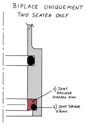
Note : seulement pour le train du Pick-Up et biplace, caler le joint racleur avec
le joint torique supplémentaire, comme ci dessous :
- Install with the same method the dust seal (No.30) in the first groove at the bottom
of the fixed leg (No.23), with Bendix grease (No.33).
Note : for the Pick-Up and two seaters only : add one O'ring to pack the scraper
ring (dust seal) as shown above.
- Enfoncer le tout vers le haut de sorte que le trou transversal du bouchon ( rep. 12 )
soit en vis ŕ vis des trous effectués en haut de la jambe fixe ( rep. 23 )
- Push everything upwars until the transverse hole in the plug (No.12) matches
the holes in the top of the fixed leg (No.23).
- Immobiliser le tout avec la broche (rep. 15) : cette broche possčde deux trous pour
la mise en place de l'épingle de blocage (rep 14). Monter cette broche avec de la graisse
pour éviter tout grippage. Attention de bien positionner la broche pour que les petits
trous destinés ŕ l'épingle soient en face de ceux réalisés dans le bouchon ( rep. 12)
- Lock the assembly with the pin (No.15) : this pin has two little holes to secure it
with a safety pin (No.14) , make sure you insert the pin (No.15) witht those little holes
matching the holes in the plug. Mount the pin with grease to avoid seizing.
- Mettre en place l'épingle ( rep. 14 ) dans les trous prévus ŕ cet effet pour
immobiliser la broche ( rep. 15 ). Monter l'épingle avec de la graisse.
- Secure the pin (No.15) with the safety pin (No.14). Mount the safety pin with
grease.
Compas
- Monter un compas ( rep. 17 ) sur la partie fixe et un sur la partie
mobile. Pour cela mettre la fourche du compas sur le support prévu, mettre l'axe ( rep.
22) en place avec de la graisse, immobiliser avec une goupille fendue ( rep. 4 ) dans le
trou prévu. Renouveler l'opération sur la partie mobile.
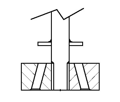
ATTENTION au sens de montage du compas ( voir le dessin ci dessus ) : lorsqu'on freine la
roue cela doit appuyer le compas de la jambe mobile contre celui de la jambe fixe, et non
pas solliciter la vis (rep.18) en traction.
- Mount one compass (No.17) on the moving leg and one on the fixed. To do so, position
the fork on the support, insert the axis (No.22) with grease, and secure the axis with a
split pin (No.4) through the hole in the middle of it.
ATTENTION : the compass must be mounted the right way up (see drawing above) : when you
brake the wheel, it must have a tendency to push the moving leg compass against the fixed
leg compass, rather than stressing the screw (No.18) in traction.
- Mettre en place l'axe ( rep. 18 ) sur le compas avec les trois rondelles laiton (
rep. 19 ). Une rondelle sous tęte, une rondelle entre les deux compas et une rondelle
sous l'ecrou ŕ créneau ( rep. 20 ). L'ecrou est ŕ serrer ŕ la main de sorte ŕ ne pas
bloquer le mouvement entre les compas.
- Fix both compass together with the screw (No.18) with 3 brass washers (No.19) : one
washer under the screw head, one between the compass and one under the castle nut (No.20).
Screw on the caslte nut by hand, (do not tighten it), to avoid seizing the compass.
- Immobiliser l'écrou ŕ créneau avec la goupille fendue ( rep. 21 ).
- Secure the castle nut with a split pin (No.21)
Support carčne de roue / wheel pant support
-sur le support carčne de roue en bas de la partie mobile, fixer les deux
embases flottantes M5 ( rep. 25) avec des rivets tęte fraisée ( rep. 24 ) aprčs avoir
fraisé les trous.
- On the wheel pant support bracket on the bottom of the moving leg, countersink the
holes for the rivets and fix the captive nuts M5 (No.25).
Remplissage des trains / Filling up the legs.
Cette opération peut s'effectuer aprčs la mise en place sur l'avion. Il est
préférable de garder les train verticaux aprčs remplissage.
This operation can be acheived after installation of the legs on the wings. It is
better to keep the legs vertical once their are filled up.
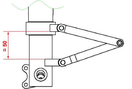
-comprimer la jambe de train de sorte que la cote entre les support de compas soit
d'environ 50 mm.
- Set the moving leg to have a distance of about 50 mm between both compass supports.
-Brancher deux tuyaux sur les valves ( l'obus doit ętre démonté au préalable ) et
remplir par un des deux tuyaux jusqu'a ce que le liquide ( rep. 31) ressorte par l'autre. ATTENTION
UTILISER EXCLUSIVEMENT DU LIQUIDE RÉPONDANT A LA NORME AIR 3520.
- Connect two hoses on the valves (the valve cores must be removed), and fill up with
hydraulic fluid (No.31) through one hose until the fluid comes out through the other
hose. ONLY USE AIR 3520 HYDRAULIC FLUID.
- mettre le train vertical et laissez-le immobile pendant 1/2 heure pour permettre aux
bulles d'air de se purger.
- Keep the legs vertical for 1/2 hour, to bleed the air bubbles.
- faire le complément de liquide.
- fill up with fluid.
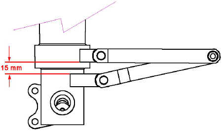
- Comprimer la jambe de train de sorte que la cote entre les supports de compas soit de
15 mm+-2.
Récupérer le liquide expulsé.
- Compress the moving leg to have a distance of 15mm +/- 2 between both compass
supports.
Collect the rejected fluid.
- Retirer les tuyaux et remonter les obus des valves.
- Remove the hoses and put the valve cores back.
BIEN ESSUYER TOUTES LES TRACES DE LIQUIDE (trčs aggressif pour les
peintures !)
CAREFULLY CLEAN ANY TRACE OF HYDRAULIC FLUID (it is very nasty for the paint !)
- Le train est pręt ŕ recevoir la pression par les valves.
- The legs are now ready to be inflated.
ATTENTION en mettant la pression car le train va se
mettre en butée détendue, il faut mettre la pression doucement ( avec un petit débit ).
Mettre une pression de 3 bars (train en butée détendue) et vérifier l'absence de fuite.
ATTENTION when inflating, because the piston is going to reach the
mechanical stop : you must inflate gradually (with a slow air flow). Inflate up to 3 bars
(mechanical stop expanded) and check for air or fluid leaks.
ATTENTION si vous devez retirer un excédent de pression, retirer
le gonfleur AVANT et dégonfler par l'une des deux valves, car l'huile en émulsion
remonte avec l'air. NE PAS SE METTRE EN FACE.
ATTENTION : if you have to release pressure, remove the tyre inflator first and press
on the valve core, because some emulsified oil is going to be blown out with air (and may
destroy components inside the manometer). DO NOT STAY OVER THE VALVES !...
Note : les repčres 5, 6 et 7 seront utilisés lors du
montage de la roue.
Note : Nos. 5, 6 and 7 will be used to fix the wheel.