
PERCAGE DU COUPLE 5 POUR SYSTEME DE VOLETS VERSION VLA
DRILLING OF Nį5 FRAME FOR VLA FLAP CONTROL SYSTEM
![]() important :
l'ensemble des perÁages est ŗ faire ŗ la perceuse ŗ colonne, en prenant un soin
particulier ŗ l'ťquerrage.
important :
l'ensemble des perÁages est ŗ faire ŗ la perceuse ŗ colonne, en prenant un soin
particulier ŗ l'ťquerrage.
![]() Important
: all the drillings must be done with a pillar drill, and checking carefully you
are perpendicular.
Important
: all the drillings must be done with a pillar drill, and checking carefully you
are perpendicular.
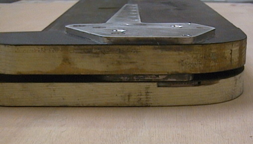
- Assembler le couple 5 et le couple 4 arriŤre gr‚ce aux trous de silentbloc.
- Assemble Nį5 frame and Nį4AR frame and align them to silentblock holes.
- Beschlšge 4 und 5 mittels Silentblockbohrungen zusammenbauen.

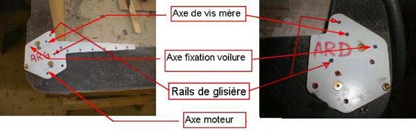
Descriptif gťnťral des percages :
General view of drillings :
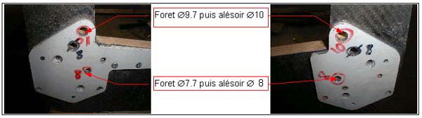
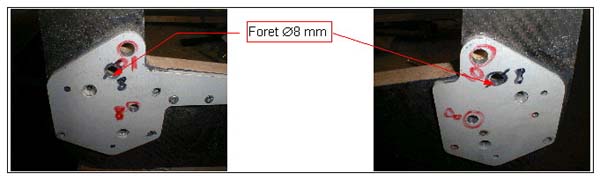
-Percer les trous D7.7 et D9.7 du chariot de volets puis alťser D8 et D10. (voir
croquis)
- Drill 7.7 mm diameter and the 9.7 mm diameter holes on the flap carriage, and ream
these holes at 8 mm diameter and 10 mm diameter (refer to the drawing).
- D7,7 und D9,7 LŲcher fŁr die Klappenmechanik bohrenanschliessend auf D 8 und D10
hohnen. (LŲcher durch Strebe 5 bis Mitte Strebe 4. Siehe Zeichnung)
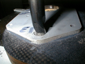
- Percer sur le couple 5 le trou de vis mŤre D8.
- Drill the 8mm diameter hole for the leading screw on Nį5 frame.
- D8 Loch fŁr FŁhrungsschraube in Strebe 5 bohren.
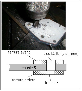
- Percer sur la face avant du couple 5 le trou de vis mŤre avec une fraise ŗ lamer
D8x16 jusqu'ŗ lťcher la ferrure arriŤre.
- Drill the lead screw hole on Nį5 frame front face using a 8x 16mm diameter spot
facing drill as far as the aft attach fitting.
- Mittels FŁhrungsfršse D8x16 Vorderseite der Strebe 5 auf D16 bis zum Anschlag des
hinteren Beschlags aufbohren.
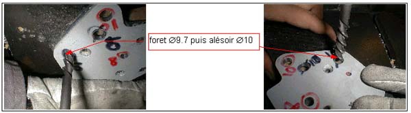
- Percer au foret D9.7 mm puis alťser D10mm les trous d'axes voilure.
- Drill 9.7 mm diameter and then ream 10 mm diameter wing axis holes.
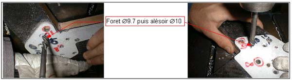
- Percer au foret D9.7 mm puis alťser D10mm les trous pour les vis mŤres.
- Drill 9.7 mm diameter and then ream 10 mm diameter leading screws holes.
- Dans la ferrure arriŤre gauche, percer D5.5 mm jusqu'ŗ mi-bois le passage d'axe du
moteur des volets.
- Drill 5.5 mm diameter hole in left aft attach fitting up to half wood thikness for
flap engine axis support.
- Lamer D13 (fraise ŗ lamer D13, pilote D5.5) juste l'ťpaisseur de la ferrure pour
installer le roulement d'axe moteur.
- Drill with 13x5.5 mm diameter spot face cutter the aliminium attach fitting
thickness in order to install engine axis bearing.
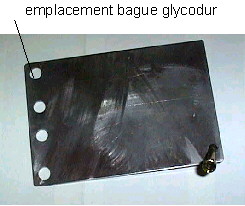
- Meuler avec l'outil les quatre bagues glycodur.
- Grind the four Glycodur inserts.
- 4 Glycodur-Ringe zurechtschleifen.
each glycodur must be 2mm long under the "head" (2+2=4 = thickness of
aluminium plate).
take a piece of plate of steel, 2 mm thick,
drill a hole the size of the glycodur,
put the glycodur in the hole,
file the glycodur flush with the metal plate, with a grinder.
- Coller les 4 coussinets glycodur ŗ collerette D8 sur les 2 ferrures arriŤres, ŗ la
colle Loctite 638 Blocpresse .
- Glue with Loctite 638 the four 8 mm diameter Glycodur inserts to the two Nį5 frame
rear attach fittings.
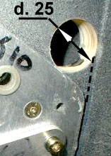
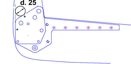
- Percez les passages des bielles dans le couple 5 :
- dia. 25 mm
- tangent ŗ la ferrure
- ŗ 5 mm de la peau de fuselage.
- Drill the holes for the rods into frame 5:
- dia. 25 mm
- tangent to the aluminium plate
- 5 mm away from the fuselage skin