
Montage des commandes d'ailerons / Aileron controls mounting
MCR Club - ULC
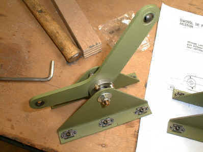
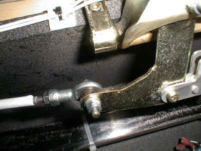
Assemblez les renvois d'ailerons sur leurs supports, en faisant un montage droit et un
montage gauche (dans cet ordre) :
Put together both aileron bellcranks, begining with the right one. :
Montez l'ensemble sur le faux longeron avec les vis CHC 4x20 et des rondelles 4x8. Le
petit bras du renvoi se met vers le saumon, le support renvoi supérieur est le plus grand
des 2.
Install this assembly on the false spar with 4*20 cylindrical & hexagonal socket
head screws and 4*8 washers. The small bellcrank leg is directed towards the wingtip, and
the upper supporting structure is the largest one.
Attention les cotes suivantes sont valables uniquement
pour le CLUB.
Warning : the following dimensions are valid for the CLUB version only.
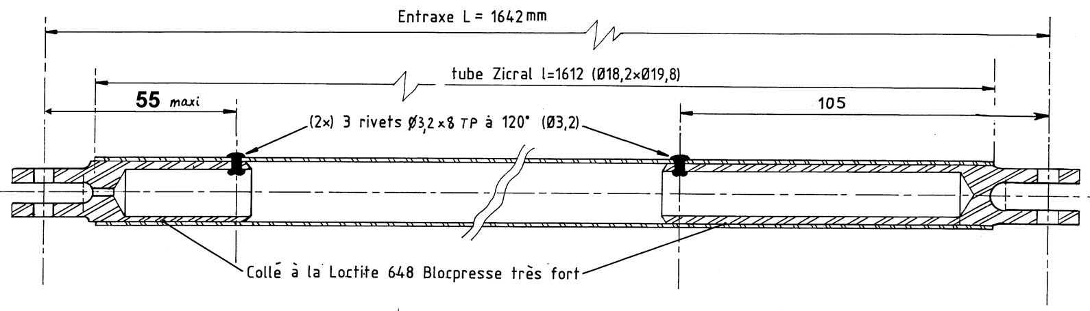
Coupez (avec un coupe tube de préférence) le tube de
la grande bielle ŕ 1617 mm (cote théorique 1612 mm + 5 mm de sécurité)
ATTENTION : cote prise au bout du TUBE et non pas ŕ l'axe de la chape.
Cut the tube on the long bellshaft leg side at 1617 mm (1612 in theory + 5 mm for
safety margin).
BEWARE : reference is being taken at the edge of the tube, NOT on the axis of the rod
end clevis.
COTES POUR L'ULC :
ULC DIMENSIONS :
Le tube de la grande bielle fait 2445mm, l'entraxe de
la bielle complčte avec ses 2 chapes vaut 2477mm.
the tube ont the long bellshaft leg side is 2445 mm long, and the distance between the
2 rod end clevis axes is 2477 mm (bellcrank fully assembled).
Enfilez la grande bielle dans l'aile et fixez-la provisoirement au
renvoi d'aileron.
Insert the long rod into the wing and attach it temporarily to the aileron bellcrank
Mettez l'aile sur le fuselage pour repérer l'endroit ŕ percer.
Place the wing against the fuselage to see where to drill.
Retirez l'aile et percez le fuselage dia. 6mm puis faites un trou de 25 mm ŕ la scie
cloche.
Remove the wing and drill first a 6 mm diameter hole in the fuselage, then a 25 mm
diameter using a bell-saw.
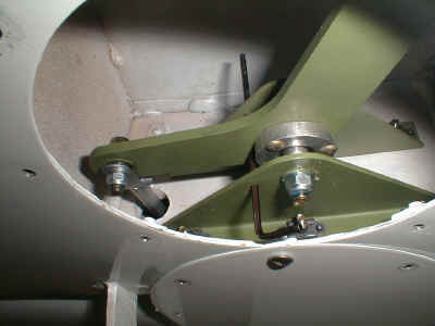
Brochez ensemble le renvoi d'aileron et ses supports avec un axe de
3 mm (clé allen par ex), pour mettre au neutre.
Broach together the bellcrank and its supporting structures with a 3 mm axis into
neutral position.
Montez la biellette sur le renvoi d'aileron (mettez suffisamment de rondelles pour ne pas
serrer l'écrou ŕ fond de filets)
Connect the smal rod to the bellshaft (use as many washers as necessary to ensure that
the nut is not reaching the end of the threads).
Montez l'aileron sur l'aile. Il faut mettre des rondelles de 5x20 de
chaque côté des rotules qui empechent celles ci de tomber si le sertissage casse.
Install the aileron to the wing. You must insert 5*20 washers on each side of the ball
bearing to prevent them from falling if the outer race casing gives up.
Réglez la longueur de la biellette en vissant / dévissant la
rotule pour que l'aileron soit au neutre. Vérifiez bien qu'il y a au moins 6 mm de filets
engagés dans la rotule.
Adjust the small rod length by screwing/unscrewing the end ball bearing so that the
aileron finds itself in a neutral position.
Check that the ball bearing is engaged over a minimum thread length of 6 mm .
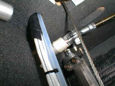
Assemblez les biellettes de commande d'ailerons : une rotule et un
contre écrou H ŕ chaque bout. La longueur théorique est de 240 mm avec les pieds de
manche anciens et 200 mm avec le pied de manche modifié (rallongé identique ŕ la
photo).
Put together the aileron control rods : an end ball bearing and an hexagonal lock nut
on each side. The theoretical length is 240 mm with the original stick bases and 200 mm
with the new ones (see picture)
Les rotules doivent ętre dans le męme plan.
Installez-les sur les pieds de manche avec le pion et l'écrou ŕ créneaux, plus une
goupille fendue.
Ball bearings must lie in the same plane.
Install them to the stick bases together with the locking pin, the castellated nut
and a split pin.
Montez la grande chape de la bielle (lg 120) sur la biellette
(intercalez des rondelles 6x12 entre la rotule et la chape).
Install the big rod end clevis (120 mm length) on the small rod (insert 6*12 washers
between the ball bearing and the clevis).
Montez l'aile sur le fuselage.
Attach the wing to the fuselage.
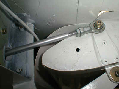
Glissez la chape dans le tube (ne pas forcer, poncer la chape si
besoin) et mettez les manches au neutre d'ailerons et de profondeur.
Insert the clevis into the tube (do not insist, abrade the clevis if required), and
hold the sticks neutral, both in roll and pitch
Mesurez la longueur de tube qu'il faudrait éventuellement couper
pour que le bout du tube soit au niveau du fond du fraisage de la chape (bord du tube ŕ 24 mm de l'axe de la chape ).
Measure the tube length you might need to cut so that its end exactly reaches the
milled bottom of the clevis.
Orientez la bielle pour que la petite chape soit au centre de son débattement angulaire,
puis orientez la grande chape sans bouger la bielle pour que la rotule soit au centre de
son débattement angulaire.
Scotchez la chape en place sur le tube.
Orient the rod so that the small clevis is right in the middle of its allowable
angular displacement, then orient the big clevis (holding the rod steady), so that the
ball bearing is also in the middle of its allowable angular displacement.
Hold the clevis in place on the tube using adhesive tape.
Libérez le renvoi d'aileron et actionnez le manche ŕ fond dans toutes les directions
pour vérifier que les bielles ne soient jamais en butée en torsion (vérifier que le
scotch n'a pas eu tendance ŕ se vriller et que les contre écrous des embouts ŕ rotule
ne sont pas désserrés).
Free the bell crank and move the stick in all (and combined) directions to make sure
no rod reaches any end stop in torsion (check that the adhesive tape isn't warped and that
the lock nuts mounted on the ball bearing ends are still firmly screwed up).
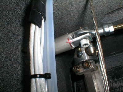
Repérez la position de la chape dans le tube (profondeur et
angle).
Remember the position of the clevis in the tube (position and orientation)
Démontez.
Disassemble
Poncez, dépoussičrez et dégraissez la chape et l'intérieur du
tube.
Abrade, remove the dust and degrease the clevis and the interior of the tube
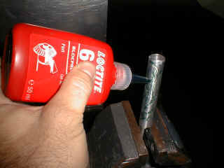
Collez la chape dans le tube ŕ sa position exacte, avec de la Loctite 648 Blocpresse.
Bond the clevis into the tube at its exact location, with " Loctite 648
Blocpresse" glue.
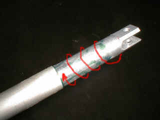
Aprčs séchage (env. 1h30), rivetez la chape au tube : utilisez 3
rivets 3.2x8 TP disposés en triangle, ŕ exactement 105 mm de l'axe de la chape (cela
laisse un espace lisse sur le tube oů les roulements du guide peuvent rouler, voir le
plan ci dessus).
Once dried out (say 1h30), rivet the clevis in the tube : use 3 3.2*8 TP rivets in a
triangular pattern, eactly 105 mm from the clevis axis apart (this allows for a
travel clearance on the tube where the bearings shall roll, see above).
Aprčs remontage, remettre les trappes.
After having put everything together again, close the access doors.
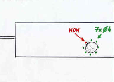
ATTENTION : un des trous de fixation se trouve dans la course du
renvoi d'ailerons : reboucher ce trou pour empecher quiconque de pouvoir y mettre une vis
par ignorance. Il y a un risque de bloquer les commandes.
CAUTION : one of the holes to bolt the door is right in the aileron control way
: fill this gap to prevent anyone from inserting a screw. otherwise there is a risk
to jam the controls.