
MONTAGE DU TRIM D'AILERONS
(sur MCR Club-ULC-4S seulement)
AILERON TRIM SYSTEM MOUNTING INSTRUCTIONS
(only available on MCR Club-ULC-4S)
1) Découpe de l'emplacement dans le revętement et installation de la charničre.
Aileron skin contouring, and hinge installation.
![]() - Au bord
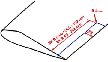
de fuite côté INTERIEUR de l'aileron DROIT, tracez un
rectangle de 28 mm de large par :
- Au bord
de fuite côté INTERIEUR de l'aileron DROIT, tracez un
rectangle de 28 mm de large par :
- 192 mm de long pour les MCR-Club et ULC
- 252 mm de long pour les MCR-4S.
- Avant de découper, mettre un rivet de sécurité 3.2x6 TP ŕ 6 mm du
bord de fuite et 10 mm de la découpe (pour éviter le décollement pendant la découpe)
- Découpez l'encoche, faites une découpe bien nette sans dents de scie, et en
particulier évitez de faire un angle vif intérieur (amorce de fissure dans le
revętement).
- On the INNER side of the RIGHT aileron trailing
edge, draw a rectangle 28 mm wide and :
- 192 mm long for the MCR-Club and ULC
- 252 mm long for the MCR-4S .
- Before you cut, put a 3.2x6 round head rivet, 6 mm from the trailing
edge and 10 mm from the cutting line (to prevent any peeling of the glue when you cut).
- Cut-out the slot for the hinge, make a straight, not dented cutting, and don't make a
sharp angle in the corner (crack start in the skin).
![]() - Retirez
la colle entre les tôles (avec une lame de scie ŕ métaux cassée) pour y installer la
charničre. (de préférence, mettre la face plate de la charničre au dessus).
- Retirez
la colle entre les tôles (avec une lame de scie ŕ métaux cassée) pour y installer la
charničre. (de préférence, mettre la face plate de la charničre au dessus).
- Protégez l'articulation de la charničre et le côté non collé, avec du scotch et de
la cire.
- Nettoyez, poncez et dégraissez les surfaces ŕ encoller.
- Collez la charničre ŕ l'époxy A-175/400.
- Maintenez en pression avec des pinces. Ne pas riveter tout de suite pour ne pas
déformer la tôle.
- Remove the glue (with a broken hack-saw blade) between the 2 skin aluminium
sheets, to insert the hinge in. (preferably, turn the flat face of the hinge
upwards).
- Protect the hinge articulation and the non-glued half, with tape and wax.
- Clean, abrade and degrease the surfaces to be glued.
- Glue the hinge with epoxy A-175/400
- Hold with plyers. Do not rivet now, you would buckle the skins.
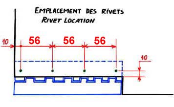
![]() - Aprčs
séchage complet de la colle (mini 24 heures), percez l'ensemble D2.5 pour mettre 4 rivets
pop (TCI repčre 12). (voir schéma).
- Aprčs
séchage complet de la colle (mini 24 heures), percez l'ensemble D2.5 pour mettre 4 rivets
pop (TCI repčre 12). (voir schéma).
- Once the glue has cured, (24 hours mini), drill through diam. 2.5mm and put 4 pop rivets (parts catalog item 12). (see drawing).
2) Montage du servo-moteur et des commandes
Servo-motor, levers and rod installation.
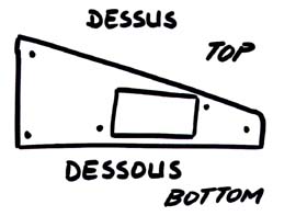
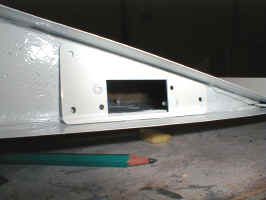
![]() - Positionnez
la plaque de support du servo sur la nervure, contre les revętements.
- Positionnez
la plaque de support du servo sur la nervure, contre les revętements.
- Tracez le trou de passage du corps de servo. (L x l = 41 x 20.5)
- Élargissez ce tracé de 5 mm devant et derričre pour pouvoir intégrer les pattes du
servo dans le trou (=> L x l = 51 x 20.5 ).
- Coupez le trou.
- Put the servo support plate on the rib, against the skins.
- Plot the hole for the servo body (Lxl = 41x20.5)
- Enlarge the cutting line by 5 mm at the front and at the back to install the servo
fixation shoulders, (=> Lxl = 51x20.5).
- Cut that hole.
![]() - Démontez
la platine du servo.
- Démontez
la platine du servo.
- Contre-percez 2 trous D3 symétriques dans la platine et le guignol
- Fixez le guignol sur la face arričre de la platine (entre le corps du servo et la
platine)
ATTENTION AU SENS !
- Fixez le servo sur sa plaque support, AVEC L'AXE A L'AVANT.
- Remove the servo link plate.
- Counter-drill two symmetric dia 3mm holes, in the servo link plate and in the aluminium
bracket.
- Fix the bracket on the rear face of the servo link plate (between the servo body and the
plastic plate)
MIND THE ORIENTATION !
- Fix the servo on its support plate, WITH THE AXIS FORWARDS.
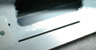
![]() - Repérez
la position de la fente pour le guignol de commande sur le débord de tôle intrados
- Repérez
la position de la fente pour le guignol de commande sur le débord de tôle intrados
- Faites une fente de 2 ŕ 3 mm de large (ou une encoche), pour laisser passer le guignol.
- Fixez le guignol sur le servo.
- Vérifiez que la fente est assez longue pour permettre le débattement complet du
guignol.
- Locate the slot for the servo control arm on the aileron intrados skin.
- Cut a 2 to 3 mm wide slot.
- Fix the control arm on the servo.
- Check that the slot is long enough to allow the full servo deflection range.
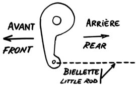
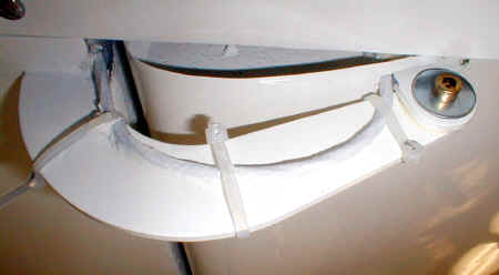
![]() - Positionnez
la potence sous la charničre, bien en face du guignol. ATTENTION AU SENS !
- Positionnez
la potence sous la charničre, bien en face du guignol. ATTENTION AU SENS !
- Contre-percez 2 trous dia 2.4 en diagonale, fraisez les trous dans la charničre.
- Fixez la potence avec une goutte de colle et 2 rivets (rep 12 TCI, ou ŕ défaut des
rivets pop)
- Put the bracket under the hinge, face to the servo control bracket and hold it
with a vise-grip wrench. MIND THE ORIENTATION !
- Drill two 2.4 mm dia. holes, on a diagonal, countersink the holes on top of the hinge.
- Fix the bracket with a drop of glue and 2 rivets (parts list item 2, or pop ones).
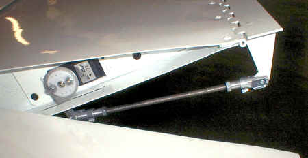
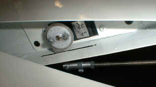
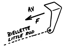
![]() - Installez
la biellette
- Installez
la biellette
- Réglez la longueur pour que la charničre soit au neutre quand le servo est au
neutre.
- Install the little rod
- Adjust its length to put the hinge horizontal when the servo is set neutral.
![]() -
Élargissez la fente ŕ l'avant de la ferrure d'articulation de l'aileron pour y passer
les fils.
-
Élargissez la fente ŕ l'avant de la ferrure d'articulation de l'aileron pour y passer
les fils.
- Installez le servo SANS LE FIXER, passez les fils dans le trou de décompression et dans
le trou devant la ferrure .
- Fixez les fils sur la potence d'aileron, et manœuvrez l'aileron ŕ fond pour
vérifiez qu'ils ne gęnent pas le débattement, et qu'ils ne glissent pas sur quelque
chose qui pourrait les couper.
- Collez les fils sur la potence d'aileron (avec une colle-joint silicone), et maintenez
avec des colliers Rilsan pendant le séchage.
- Une fois que vous ętes SUR que vous n'aurez pas ŕ le démonter, fixez la plaque
support servo sur la nervure, avec 3 rivets pop dia. 3.2x6 TP. On conseille de ne pas
coller la plaque. Si besoin, pour démonter le servo, percer les rivets.
- Enlarge the slot in front of the aileron articulation bracket, in order to drive
the wires through out.
- Install the servo BUT DON'T FIX IT, drive the wires through the vent hole and through
the hole in front of the bracket.
- Fix the wires on the aileron bracket, and move the aileron up and down to check that
they don't disturb the deflection range, and that they don't slide on something that woud
cut them.
- Glue the wires on the bracket (with a silicon adhesive), and hold with plastic rings
during curing.
- Once you are SURE that you won't have to remove it, fix the servo support plate on the
rib, with 3 3.2x6 round head pop rivets. We don't advise to glue the plate : if necessary,
to remove the servo, drill the rivets.