
COMMANDE de TRIM MCR-4S
MCR-4S TRIM CONTROL SYSTEM
[mise ŕ jour / update 01/2003]
SYSTEME ABANDONNE AU
PROFIT DU "SERVOTRIM" DANS LA DERIVE
A PARTIR DE MARS 2008
SYSTEM ABANDONED AND REPLACED BY A SERVOTRIM IN THE FIN FROM MARCH 2008
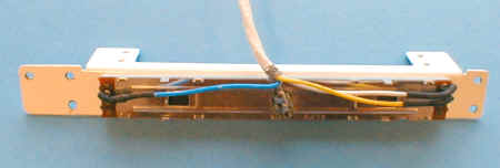
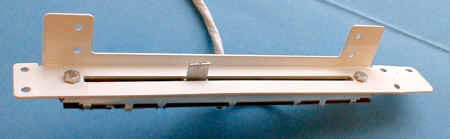
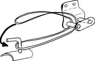
Assemblage du mécanisme du trim.
Trim mechanism assembly.
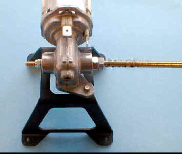
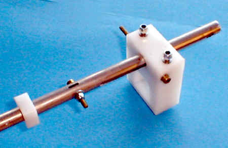
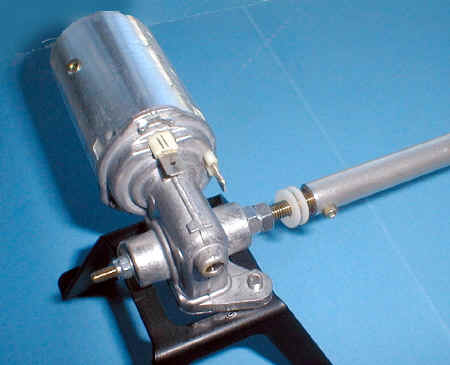
- Montez la vis sans fin sur le moteur électrique. Repérez bien
l'orientation sur la photo.
- Assemble the lead screw on the electric motor. Look at the picture to see the
orientation.
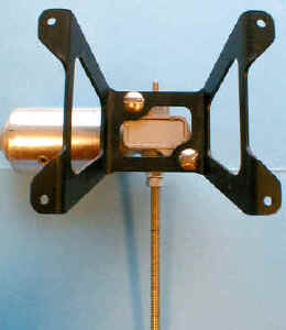
- Montez le moteur sur son support, en faisant attention au sens de
montage : orientez le support pour que l'axe de la vis soit centré. (voir photo). Bloquez
les deux vis poelier de fixation avec de la colle Loctite 243 Freinfilet.
- Mount the motor on its support, minding its orientation : the lead screw must be
centered over the suppport legs (see picture). Secure the two poelier screws with Loctite
243 glue.
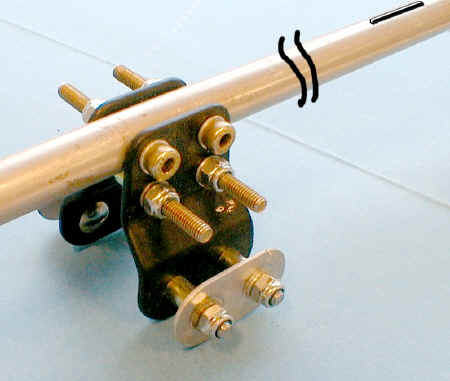
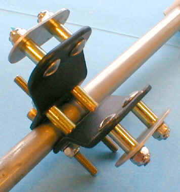
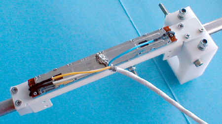
- Montez les attaches d'élastiques sur le tube. Attention : repérez
l'orientation par rapport ŕ la petite encoche de 2 mm sur le dessus du tube.
- Fit the rubber band attachment brackets on the tube. Mind the orientation with the small
2mm wide notch on the top of the tube.
Note : le potentiometre est une option, il n'est utile
que si vous souhaitez un "répétiteur" de position de trim au tableau de bord.
Note : the potentiometer is optional, it is useful only if you wish to have a trim
setting indicator on the instruments panel.
- Avec une pince coupante, raccourcissez le
curseur du potentiometre de 3mm.
- with cutting plyers, shorten the potentiometer cursor by 3mm.
- Montez le potentiometre sur le support des switches
de fin de course. Fixez les vis ŕ la Loctite Freinfilet.
- Fix the potentiometer on the end swich support. Secure the screwws with Loctite 243.
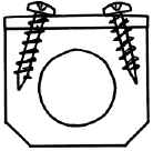
- Repliez délicatement la languette des swiches, comme
sur le dessin.
- Fold with care the switch lever, as indicated on the drawing above.
- Rivetez les switches de fin de course sur le support.
Note : il est normal d'aggrandir les trous de fixation (D. 2.4mm). Mettez la tęte
du rivet côté switch, pour ne pas l' "éclater".
- Rivet the end switches on the support. Note : you have to re-drill the swithc fixation
holes D. 2.4mm. Put the rivet head on the switch, otherwise you could burst it.
- Enfilez le guide PolyEthylčne avant sur le tube
- Slide the front PolyEthylene guide on the tube.
- Montez le guide PE arričre et montez la vis de
bloquage en rotation dans la fente. ATTENTION au sens : la vis se met vers
l'avant, du côté du moteur.
- Slide the rear PE guide on the tube, and lock the rotation by installing
the screw through the long notch. MIND THE ORIENTATION: the screw must be on the front,
towards the motor.
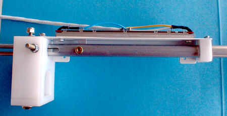
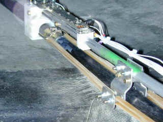
- Positionnez le support de switchs sur les deux guides
en PE, en emboitant le curseur du potentiometre dans la petite fente du tube.
Contre-percez les trous de fixation Dia. 2mm. Percez légčrement en diagonale, pour
éviter que la vis touche le tube. Vissez avec des petites vis parker
- Put the switch support on the two PE guides, with the potentiometre cursor fitted into
the little slot in the tube. Counterdrill D. 2mm the fixation holes. Drill diagonally so
that the screws escape the tube. Screw with the small parker screws.
- Montez la vis de 4 mm , qui actionne les switchs de
fin de course. Mettez la partie filetée du côté des switchs.
Note : la vis CHC 4x25 (TCI QPL2701 rep 4 - 12)sur le tube
qui sert d'actionneur aux swichs est représentée ŕ l'envers sur le TCI : monter la vis
avec la partie filetée qui dépasse du côté des swichs.
- Screw the 4 mm bolt that make the contact on the end switchs. Put the threaded end
on the switch side.
Note : this CHC 4x25 screw is drawn in the wrong direction on the parts list. Mount
it with the threaded part protruding on the switch side.
- Testez le fonctionnement : les switchs doivent faire
contact (on entend "clic") nettement avant que le systčme arrive en butée
mécanique (minimum 2 mm). Au besoin ajustez les pattes des switchs.
- Test the switchs : they must contact (you hear the "click") markedly
before the system is on the mechanical stop (minimum 2 mm). If required, adjust the switch
levers.
- Mettez deux rondelles en plastique (6x14) sur la vis
mčre et vissez-la dans le tube.
- Insert 2 plastic washers (d. 6x14) on the lead screw, and screw it in the tube.
Installation dans l'avion et réglage
Installation and setting
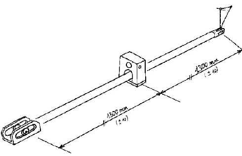
- Maintenir le manche ŕ mi-course, et repérer sur le
fond du fuselage le milieu de la grande bielle de profondeur. (ŕ 1300 mm depuis l'axe des
roulements)
- Hold the stick at mid-range. and draw a mark on the fuselage floor in front of the
middle of the big rod. (1300 mm from the ball-bearing axis)
- Monter le guide bielle en PE (en forme "d'arc de
triomphe") au centre de la bielle de profondeur, en intercalant son socle entre la
bielle et le fond de fuselage. Utilisez des vis ŕ tete fraisée de 4x70, avec une
rondelle cuvette sous la tęte, contre le fuselage.
- Fix the PE rod guide ("Arc de Triomphe" shape) on the middle of the main
rod, with its base wedged between the rod and the fuselage skin. Use countersunk head 4x70
screws, with a conic washer under the screw head, against the fuselage skin.
- Positionnez (sans le fixer définitivement) le suppot
moteur au fond du fuselage, les trous de fixation arričres doivent ętre ŕ 490 mm de la
face avant du guide.
- Position the motor support (but don't fix it for the moment) on the
fuselage floor. the rear holes must be 490 mm from the front face of the PE guide.
- Vérifiez que dans cette position, quand le
switch avant est en contact, il reste quelques mm de course entre le tube et les
contre-écrous du moteur
- Check that, in that position, when the front switch is in contact, it remains a few
mm clearance between the tube and the motor set-nuts.
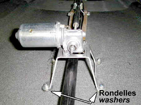
- Fixez le support au fuselage avec des vis poęlier.
Intercalez des rondelles larges sous les pattes avant pour ne pas contraindre la vis mčre
en flexion.
- Fix the support to the fuselage with poelier screws. Wedge the front legs with large
washers to avoid stressing the lead screw in flexion.
Fixation des élastiques
Rubber-band fixation
Positionner les crochets ŕ élastiques sur la bielle
de profondeur :
Position the rubber band hooks on the rod :
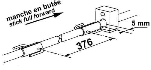
- Maintenir le manche en butée avant.
- Hold the stick forward.
- Positionner les crochets arričre en laissant 5 mm de
jeu entre le bord arričre du tube des crochets et le guide-bielle en PE. Tracer leur
position et maintenir en place provisoirement avec des colliers rilsan.
- Position the rear hooks on the rod : leave 5 mm clearance between the rear edge of
the tube and the front face of the PE guide. Mark tho position and hold them
temporary with a plastic hose clamp
- Retirez la bielle
- Remove the rod
- Positionnez les crochets avant ŕ 376 mm des crochets
arričre (distance d'axe ŕ axe).Tracer leur position.
- Position the front hooks 376 mm in front of the rear ones (distance from axis to
axis). Mark their position
- Dépolir la bielle en carbone au SCOTCH-BRITE (pas de
papier de verre)
Poncer l'intérieur des crochets : papier ~= 150 -
240, griffer la surface sans retirer le cadmiage.
dégraisser soigneusement
- Grind the carbon rog with SCOTCH BRITE (not sandpaper)
sandpaper the inner face of the hooks : use ~=150/240 sandpaper, scratch the surface
without removing the cadmium coating.
degrease carefully
- Coller ŕ la colle époxy A-175/400. Mettre
sous pression ŕ l'aide des colliers "serflex" EN SERRANT TOUT DOUCEMENT.
Attention si on serre trop on peut casser la bielle !
Retirer l'excédent de colle, mais laisser un
petit bourrelet devant et derričre, sur le tube, pour qu'il agisse comme une butée au
cas oů.
NE PAS RIVETER ! Note : les colliers serflex ne
doivent pas ętre retirés.
Aprčs séchage de la colle, les resserrer légčrement
avant de ré-installer la bielle.
- Glue the hooks with epoxy glue A-175/400. Press with hose clamps BUT TIGHTEN
VERY GENTLY. Be careful because you may break the carbon rod by pressing too much !
Remove the glue in excess, but leave a small
glue roll on each side ot the hooks, on the tube, it will act as a stop, just in case.
DO NOT RIVET THEM ! Note : the hose clamps must
stay on the rod.
Once the glue is dry, re-tighten them gently
before you put the rod back in the fuselage.
- Tendre un élastique de 150x10 entre chaque crochet
et le support correspondant. Les élastiques doivent ętre posés "en double" :
- Bend one 150x10 rubber band between each hook and the corresponding support. The
rubber bands must be fitted "double" (see drawing).