
FIXATION DES FERRURES D'ARTICULATION ET DE COMMANDE DE L' EMPENNAGE
HORIZONTAL
TAILPLANE CONTROL ROD AND HINGE BRACKETS FIXATION
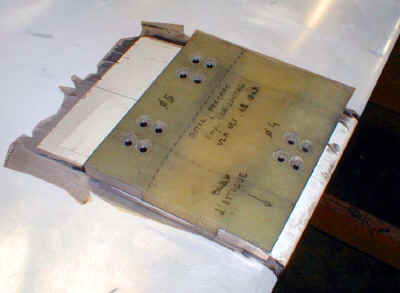
Tous de fixation des ferrures
Bracket fixation holes
- Emboiter les pions de l'outil de percage dans les deux trous de 4 mm ŕ l'intrados de
la gouverne.
- Position the drilling template on the tailplane intrados, thanks to the two 4 mm
holes.
- Percer les trous.
- Drill the holes.
Trous d'accčs aux écrous
Nut access holes
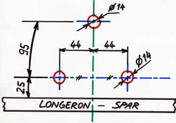
- Repérer et tracer sur la tôle la position du longeron (cote parallčle au plan de
l'aile).
- Trace on the skin the spar position (the dimension is given parallel to the chord).
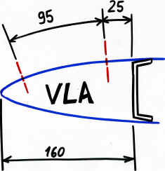
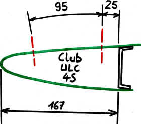
- Tracer la position des trous d'accčs aux écrous ŕ l'extrados, ŕ l'aide du gabarit
ou des cotes ci-dessus (cotes DEVELOPPEES le long du profil).
- Trace the hole positions on the upper surface, with the template or with the
dimension given above (dimensions are to be taken along the tailplane profile).
- Percer les trous diametre 14 (de préférence avec un foret ŕ étages, ou une fraise
ŕ lamer). attention, n'endommagez pas l'intérieur du squelette).
- Drill the 14 mm holes (preferably with a spotfacing drill, or a stepped drill).
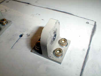
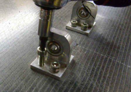
Fixation des ferrures
Bracket fixation
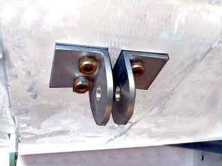
- Cirer les quatre vis et les quatre écrous.
- Wax the four screws and nylstop nuts.
- Monter les fixations bielle profondeur sur l’empennage : poncer au papier 120 et
dégraisser, coller ŕ l'Epoxy A-175/400 et visser en serrant modérément (laisser 2 ŕ 3
10čmes pour la colle)
- Bond brackets to the tailplane with Epoxy Glue (previously abrade with 120 sand paper
and degrease) and secure it (tighten the screw moderately, to leave a 2/3 10th mm for the
glue).
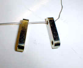
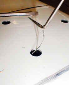
- Passez un fil ŕ freiner (30 cm) dans deux écrous spéciaux
- Pass a safety wire (30 cm long) through two special nuts.
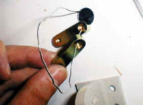
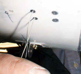
- Glissez les écrous ŕ l'intérieur de la gouverne et passez les deux
bouts du fil ŕ freiner dans deux trous de fixation.
- Insert the two nuts inside the tailplane, and pass the two wire ends through two
fixation holes.
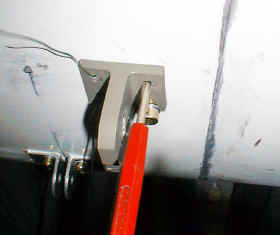
- Présentez la ferrure,
- Alignez les trous et l'écrou (ŕ l'aide d'une pointe ŕ tracer par exemple),
- Maintenez l'écrou en place en appuyant dessus (en passant un tournevis par le trou de
14),
- Engagez les vis.
- Install the bracket,
- Align the holes and the nut (with a scribe for example),
- Hold the nut pressing on it with (with a screw diver, through the 14 mm hole),
- Engage the scews.
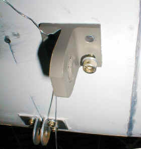
- Retirer le fil ŕ freiner et mettre les deux autres vis.
- Remove the safety wire and engage the two other screws.
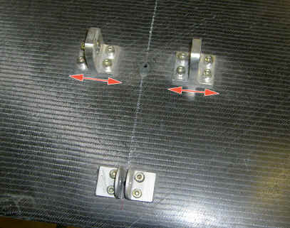
- POUR LE MOMENT LES VIS NE
DOIVENT PAS ETRE SERREES pour permettre aux ferrures de se déplacer légčrement
latéralement, pour s'adapter dans les ferrures de fixation du fuselage sans contrainte.
Reportez vous ŕ la gamme de fixation de l'empennage sur l'avion pour la suite. (pour
biplace: suivre ce lien, pour MCR 4S suivre ce lien).
- DO NOT TIGHTEN THE SCREWS AT ONCE, to allow the brackets to move sideways a
little bit, to fit freely without stress between the brackets on the fin .
Refer to the instructions to fit the elevator to the fin for the end of the operation.
- Boucher les 3 trous de 14 avec les capuchons plastique.
- Obturate the three 14 mm holes with plastic caps.